 en
en
 Русский [ru]


Carefully read the contents of this manual, it will help you avoid breakdowns and injuries!
- Security.
- Types of seals.
- Description.
- Options.
- Creating connections.
- Directions.
- Intended use.
- Storage.
- Before installation.
- Auxiliary means.
- Installation.
- Creating connections.
- Exploitation.
- Emissions.
- Reliable operation.
- Safety of workers.
- Technical maintenance.
- Problems.
- Orders.
- Service.
- Dismantling.
- Current setup work.
- Spare parts.
- Resuscitation of used mechanical seals.
Security.
Every employee who engages in the installation, dismantling, servicing and commissioning of KROMA Ltd face seals in the user's enterprise must read and understand the operation manual or at least the required section of the manual.The mechanical seals of KROMA Ltd have high quality (IS0 9001) and are reliable in operation. The use of mechanical seals can be dangerous if seals are not used for their intended purpose, if they are not mounted by specially trained personnel or if they are not used by qualified personnel.
The operator needs to monitor, within the framework of his safety concept, the environmental consequences of the failure of the mechanical seal and what additional measures should be taken to protect personnel or the environment.
The operating mode leading to a decrease in the reliability of the equipment operation is inadmissible.
Only authorized, specially trained and properly instructed personnel are allowed to build, maintain and maintain mechanical seals for KROMA Ltd. In principle, all work on mechanical seals is carried out only on equipment that is at rest and in the absence of pressure. In order to avoid ambiguity regarding the competence in security matters, they should be clearly delineated and strictly observed.
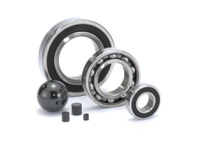
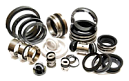
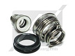
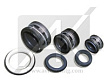
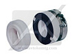
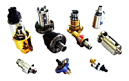
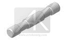
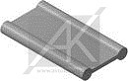
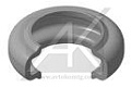
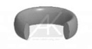
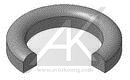
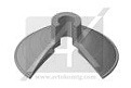
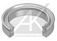
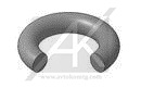
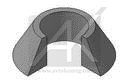
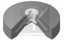
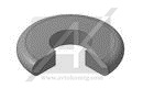
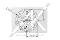
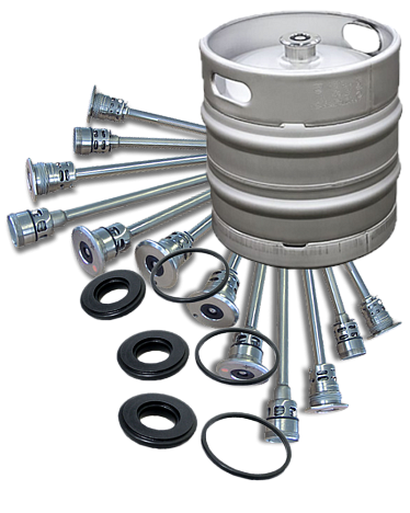
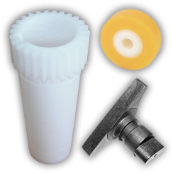
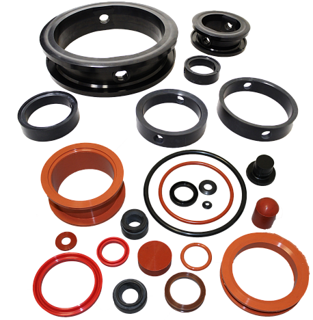
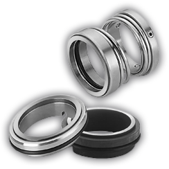
Types of seals.


Position - Name:
1 - countercross
2 - O-ring
3 - spring
4 - rotating ring
5 - O-ring
6 - bushing
7 - O-ring
8 - ring for fixation
9 - screw ring for fixing
10 - stopper
11 - housing
Product pressure and sliding speed.

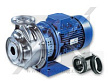
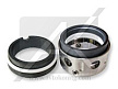
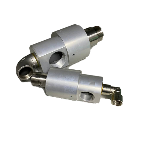
Description.
Type UCA:
- single seal;
- hydraulically discharged;
- does not depend on the direction of rotation;
- without connections.
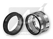
Type UCB:
- single seal;
- hydraulically discharged;
- does not depend on the direction of rotation;
- with a washing line.
Type UCC:
- single seal;
- hydraulically discharged;
- does not depend on the direction of rotation;
- with flushing and cooling.
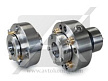
Type UCD:
- double seal;
- hydraulically discharged;
- does not depend on the direction of rotation.

Options.
Pressure:- p = 25 bar.
Temperature:
- t = -40...110°С (NBR);
- t = -50...150°С (EPDM);
- t = -20...180°С (FKM);
- t = -20...250°С (FFKM).
Rotational speed:
- v = 25 m/s.
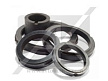
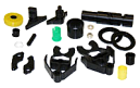
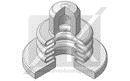
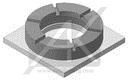
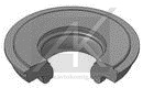
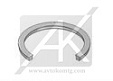
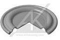
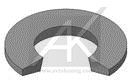
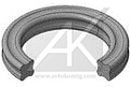
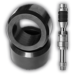
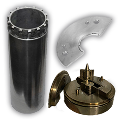
Position - Name:
1, 14 - countercross
2 - O-ring
3 - spring
4, 17 - rotating ring
5 - O-ring
6 - bushing
7 - O-ring
8 - ring for fixation
9 - screw ring for fixing
10 - stopper
11 - enclosure
12 - gasket
13 - screw
15 - O-ring
16 - screw
18, 19 - O-ring
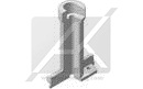
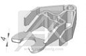
Creating connections.
Horizontal location:"VENT" (ventilation) must be on top. Use attachments depending on the direction of rotation of the shaft "IN" (input), "OUT" (output) to change accordingly.

Vertical layout:
Use attachments depending on the direction of rotation of the shaft. "VENT" (ventilation) here does not matter. "IN" (input) must always be at the bottom, "OUT" (output) must always be on top.

Directions.
Operation that violates the limits of the operating range is not the intended use. Observe the interaction of these boundaries, i.e. To exclude simultaneous use of all maximum parameters. The technical data is based on a number of different tests and our many years of experience. However, in view of the large number of possibilities of application, they should be considered as indicative parameters.
The choice of the operating principle ("dead-end", with a liquid seal or as a double seal) also depends on the conditions of use and on the basic value for the function and safety of the mechanical seal. Guarantee in a separate case is possible only if we know the exact terms of use, which were also agreed in a separate written document. If there is any doubt, you should consult KROMA Ltd before commissioning.
We reserve the right to technical changes, also if they have not been taken into account in this manual.
Intended use.
Operation beyond the conditions listed in "BOUNDARY OPERATION PARAMETERS" is considered to be an operation that does not meet its intended purpose. If the mechanical seal is intended for other operating conditions or for another place of operation, KROMA Ltd.
Storage.
KROMA Ltd face seals are high-precision and controlled machine elements, handling of which before and during storage (especially for spare parts) requires special measures (see also DIN 7716 for elastomers).
Slip properties and elastomers are exposed during storage to materials-specific changes that depend on the shelf life (aging, warpage), which may limit the full functionality of the mechanical seal. In this regard, you should strictly follow the storage instructions.
Seals should be stored in the original packaging, on an even lining.
Storage room for mechanical seals:
- dust-free;
- little ventilated;
- with uniform temperature support;
- relative air humidity below 65%;
- temperature from 15°С to 25°С.
The mechanical seal is protected against direct exposure to heat by heating, sun, ultraviolet light, halogen or fluorescent lamps, sunlight, due to the threat of embrittlement of elastomeric materials.
Mechanical seal monitoring:
- at the expiry of the shelf life of approximately 2-3 years;
- if the packaging is damaged;
- under impact load (eg, falling of a packed seal);
- at the manufacturer or at the nearest service center.
KROMA Ltd is not responsible for damages caused by improper storage of seals.
This instruction is valid both for KROMA Ltd mechanical seals, supplied and stored in the original packaging of the manufacturer, and for seals that are already integrated into one of the equipment components (pump, compressor, agitator, etc.), but not yet introduced in operation.
A preservative is not required to be applied to the cartridge of the cartridge.
Do not use anticorrosive protection.
The danger is the formation of precipitation and, possibly, the chemical effect of elastomeric auxiliary seals.
When all equipment with integrated mechanical seal is preserved, check:
- compatibility of selected preservatives with construction materials and elastomers of mechanical seal;
- no interference with the installation / correction movements of the mechanical seal caused by possible adhesion and gumming.
Before installation.
ATTENTION! Do not unpack the seals until the following operations are fully completed.
Control of the units on the machine side:
- bevelled edges (chamfer 2 mm / 30° or to DIN 24960);
- rounded junctions;
- calibrated landing;
- surfaces under O-rings: sized to Rz 10 (DIN 4768).
The outer surface of the shaft in the area of the mechanical seal:
- depth of microroughness Rmax 5 μm.

Check the machine for:
- presence of damage on the surfaces of the seal of the mechanical seal;
- connection parameters, orthogonality and absence of radial runout with respect to shaft axis.
Rolling of the shaft relative to the face of the seal chamber (according to DIN ISO 5199):
- shaft diameter up to 50 mm, maximum runout of 0.05 mm;
- shaft diameter 50 mm - 100 mm, maximum runout of 0.08 mm;
- shaft diameter is more than 100 mm, the maximum runout is 0.10 mm.
Preliminary it is necessary to prepare a place for installation, that it was free from unnecessary tools, shavings, dirty rags, and also to lay the instrument table with a piece of clean, non-fuzzy cardboard.

Auxiliary means.
- propyl alcohol;
- paper handkerchiefs (not rags!);
- grease for seals made of elastomers;
- a set of hexagonal spanners with pins (SW2 - 6 mm).
Installation.
The mechanical seal is a cartridge, pre-assembled in the factory with precise alignment, designed for mounting without adjustment.
When assembling, use the assembly drawing.
Installation of the mechanical seal should be carried out in absolutely clean conditions and carefully.
Round seal rings, which slide into or on other components when the mechanical seal is inserted, can be lubricated with a very thin layer of lubricant.
Sealing elements made of ethylene-propylene rubber should never come in contact with lubricants containing mineral oils (swelling, decomposition possible).
Sequence of installation insertion operations (API 640/682):
UCC - Strapping plan №61:
1 - Closed wash output
2 - Closed wash inlet

UCC - Strapping plan №62:
1 - External flushing, from an external source.

UCD - Strapping plan №52:
It is required to supply a return fluid from a pressure-loaded backup tank in accordance with API 610/662, plan 53, or from a non-pressure reserve tank according to API 610/682, plan 52/54, or from a dead-end receiver, according to API 610/682, plan 51. Circulation of liquid with a rotating shaft by means of an integrated in the T.U. feed systems.
Circulation connections, return fluid "EIN" (input) and "AUS" (output) according to the direction of rotation of the shaft (see drawings).

The external reservoir for liquid is not under pressure. Thermosyphon or, if required, forced circulation.
1 - If included in the specification
(PS = pressure meter)
(PI = manometer)
(FI = flow indicator)
2 - Usually open
3 - Pouring nozzle
4 - Level gage
5 - Storage tank
6 - If included in the specification
7 - Drain valve
UCD - Strapping plan №53:

The external reservoir for the liquid is pressurized. Thermosyphon or, if required, forced circulation.
1 - If included in the specification
2 - External pressure source
3 - Usually open
4 - Pouring nozzle
5 - Level gage
6 - Storage tank
7 - If included in the specification
8 - Drain valve
Creating connections.
The conclusions of the supply system are the NTP - threaded terminals / fittings.
The conclusions for the connection of supply lines on the mechanical seal have a special marking and they can not be confused with each other.
ATTENTION! The means of sealing the thread (PTFE tape, etc.) pose a danger to the reliable operation of the mechanical seal in case they come into the seal.
For feeder piping, only such sealing means should be used that can not enter the mechanical seal, for example, when threaded connections are loosened.
Supply lines:
- stainless steel pipes of large cross section;
- clean pipes thoroughly;
- tighten the pipe bolted connections securely.
UCD:
In addition to the shut-off circulation system, the following applies:
- pipes should be laid with a constant lift, as short as possible and streamlined;
- avoid the formation of air bags, if necessary, provide air inlet connections;
- do not use the connecting holes tightly close with threaded plugs.
Exploitation.
Safety control before commissioning:
- the mounting calibers from the mechanical seal are removed, the torque transmission (pin No. 9) from the mechanical seal to the shaft;
- the interconnection of supply systems ("UCC", "UCD") is hermetically and tightly tightened;
- the integration of waste disposal systems is environmentally safe;
- the pump and the seal cavity (the gland cavity) are filled with a working medium;
- the air is carefully vented from the seal cavity and the circulation system;
- the cavity of the liquid shutter, or the shut-off cavity ("UCC", "UCD") are completely filled with circulating liquid and air is carefully discharged from them;
- the process of air release after a short period of operation is repeated many times at a stopped pump.
With vertical positioning (UCC, UCD):
- through the opening in the cover (11), gently push down for a short time with a suitable tool a sliding ring from the side of the atmosphere (15) in order to completely discharge the air from the mechanical seal.
In the operating mode according to API 610/682, plan 53 (UCD):
- set the shut-off pressure by a value of at least 2 bar, in addition, about 10%, depending on the pressure level, above the maximum pressure in front of the face seal of a constant value (take into account the maximum pressure pmax);
- the final operation of the mechanical seal is possible only if there is a blocking pressure;
- seal ready for use.
Emissions.
The mechanical seal is a dynamic seal that can not be completely sealed (no leakage). Leak during normal operation is very low.
The leak may be gaseous or in the form of a liquid. It corresponds in its aggressiveness to a locked environment.
UCC:
Minor fluid leakage of the liquid seal is possible through the throttle ring to the atmosphere.
Nodes in contact with a leak must be corrosion-resistant or they must be adequately protected.
Inspection of mechanical seals is carried out as part of an audit.
Reliable operation.
UCC:
The safety prescribes that the temperature of the circulating fluid should not exceed 80°C, or at least it must be 40°C below the boiling point at the normal pressure measured on the pipeline near the outlet of the mechanical seal. Adjusting the temperature by cooling the liquid in the reserve capacity of the supply system.
UCD:
The shut-off pressure must be in any operating mode above the product pressure.
ATTENTION! If the pressure of the gate liquid falls below the pressure in the pump, the medium to be sealed flows through the sliding surface into the closure fluid. The liquid is contaminated. It is recommended that regular inspection and replacement of the fluid.
Safety of workers.
If the seal fails, the sealing medium can be sprayed outwards. The operator must take appropriate measures to protect human health and the environment, such as by applying splash protection, wearing safety goggles, etc., and to monitor their performance.
Technical maintenance.
With proper operation, the mechanical seal requires little maintenance. Wearing parts, however, must be replaced if necessary.
UCB:
To ensure the reliable operation of the mechanical seal, we recommend that the most suitable of the types of circulation described in API 610 be used on the product side. This measure prevents the deposition of the product in the sealing zone.
UCC:
The appropriate operation of the mechanical seal includes control:
- temperature of the shut-off working fluid (max 60°C at the outlet of the mechanical seal);
- reserve of sealing working fluid;
- leakage (drainage) in the mechanical seal.
UCD:
The appropriate operation of the mechanical seal includes control:
- the level of the prescribed gate valve fluid pressure;
- filling liquid level in the thermosyphon;
- color of the gate liquid;
- leakage (drainage) from the mechanical seal;
- flow of cooling water installed to ensure that the temperature of the gate liquid on leaving the TU does not exceed 80°C.
Inspection of mechanical seals is carried out as part of equipment revision. Recommended examination of the condition of mechanical seals by a responsible visiting representative of KROMA Ltd.
Problems.
In case of problems that can not be solved by yourself, or if it is not possible to determine the exact cause of the problem, contact the relevant KROMA Ltd field service immediately, with KROMA Ltd service or directly with KROMA Ltd.
During the warranty period, the dismantling of the mechanical seal of KROMA Ltd is permissible only with the permission of the manufacturer or in the presence of one of the representatives of the company.
Orders.
For inquiries and orders please indicate the following data:
- KROMA Ltd - commission №;
- № mechanical seal drawing: UC....;
- № item positions, name, material, quantity.
Service.
The service department of KROMA Ltd offers an extensive package of services, ranging from advice and advice, engineering, standardization, installation, commissioning to fault analysis and holding seminars on seals. You can find the address list in the well-known construction catalogs of KROMA Ltd, as well as other printed editions of KROMA Ltd.
Dismantling.
• In accordance with the instruction of the pump, stop, cool and remove the pressure.
• The product on the mechanical seal is absent - the pump, if necessary, is emptied!
• Protect the pump from unintentional activation!
• Observe the safety instructions (safety data sheets)!
If the sealing medium forms a coating or freezes upon cooling and simple machine, rinse the seal cavity with a clean liquid. Quantity and type of liquid at the discretion of the operator.
Gas seal cartridges should be tried during the removal of the cartridge or after that, if possible, do not disassemble and as little cleaning as possible so that the qualified personnel of the manufacturer or the operator can make it easier or even possible to assess the type of damage and the causes of their appearance.
When dismantling the mechanical seal cartridge, follow the safety instructions; In addition, the requirements for the handling of hazardous materials should be considered and complied with in the event that the mechanical seal has already been in use. If there are any ambiguities, you should ask for the required information before starting the repair.
Basically, all work on mechanical seals are carried out only on equipment that is at rest and in the absence of pressure.
The sequence of dismantling operations of the mechanical seal from the pump is oriented to the corresponding design of the pump and it is considered expedient if the sequence of dismantling operations is established by the pump manufacturer.
• Remove pressure and close supply system (or empty).
• Dismantle supply pipelines.
• Pins with annular cutting edges (9) must be removed and discarded.
ATTENTION! The studs with annular infeed edges may only be used once. Re-tightening adversely affects the transfer of labor force.
Dismantling of the mechanical seal is similar to the installation, however, in the reverse order.
Current setup work.
If it is necessary to repair the mechanical seal, the manufacturer is sent the entire cartridge of the mechanical seal. Here, the best estimate can be made of which nodes can be treated further, or where replacement of seal elements is necessary in order to ensure optimum sealing of equipment.
In the event that repairs for urgent reasons are to be carried out at the site of operation of the mechanical seal (for example, no spare compaction, long transport, customs problems), the repair can be carried out by trained operating personnel in a clean room under the guidance of the KROMA Ltd.
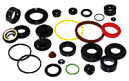
Spare parts.
Only original parts of KROMA Ltd. can be used. Otherwise, there is a risk of malfunctioning the mechanical seals with possible danger to human life and the environment, and the product is no longer guaranteed by KROMA Ltd. To accelerate the replacement it is recommended to stock up one complete spare seal.
Resuscitation of used mechanical seals.
Usually used KROMA Ltd face seals can be easily removed:
- metal parts (steel, special steel, non-ferrous metals), divided by grade, refer to scrap metal;
- synthetic materials (elastomers, PTFE) are classified as special waste;
- individual materials can be appropriately sorted and re-processed (recycling);
- ceramic elements (coal, ceramics, carbide) can be separated from the raw materials and removed as garbage. Due to the fact that they are physiologically harmless, they can be isolated from load-bearing materials.
ATTENTION! Materials containing fluorine can not be burned!


